
Histology Image Reconstruction
A short introduction
To create a 3-D histology image reconstruction is far from merely stacking the images. After digitization, the individual slice images usually have different orientations. Trying to observe structures and their progression along the stack is cumbersome, as their location jumps from slice to slice.
Rigid Alignment
The first step is therefore a rigid alignment step. Rigid means, that only the orientation of the slide is changed such that they show the same alignment. Now, the shape of the object is already visible, and browsing through the data set becomes easier. However, now the individual slice deformations become more apparent. There are still jumps and offsets of originally smooth structures, which disturb the visual impression.
Image unwarping
The coherence of the data set, the connection between corresponding structures and the final step is therefore a non-rigid registration process. Here, the slice images are individually slightly warped and deformed, so that in the end slice elements that once belonged together, fit together again. This step therefore restores the spatial coherence of the data set, smoothing structures and restoring connectivity. Browsing through the data set now looks like a movie, moving along the image stack.
Defects Affect Quality
Unfortunately, the histological preparation introduces various and sometimes severe artifacts, e.g.
- tears
- missing elements
- inhomogeneous staining
- wrong sequence
These artifacts affect the ability of the underlying algorithm to find the best fit. Depending on the severity of these artifacts, the overall reconstruction quality will be degraded. We therefore recommend to first discuss potential drawbacks of your data before the reconstructions. In addition, the first test reconstruction - which is part of our projects - can also help to assess potential problems.
High-Resolution Reconstruction
The mother of all questions - how high can we go?
In an ideal world, we would like to chose the highest magnification possible and look into the tiniest details from all sides. Unfortunately, the more “high-resolution” one wants to achieve, the trickier it gets.
One key aspect to consider is that one is inherently limited by the chosen slice thickness. In the final 3-D volume image, the size of one image element - a voxel - is defined in x and y by the pixel size of an individual image, and in z (the depth or thickness) by the slice thickness.
An example:
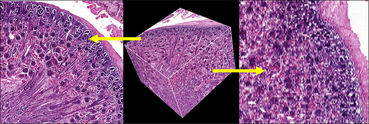
Your imaging scanner might have - at 40x magnification - a resolution of 0,225µm x 0,225 µm per pixel. The slice thickness was chosen 4µm. So each individual volume element will have the dimensions 0,225µm x 0,225µm x 4µm. But this in turn means, that every voxel is 16 times as long (along the stack) as it is within the slice plane (40x magnified image)! This is a significant disadvantage in visualization. The following image demonstrates this resolution mismatch.
In addition, when slices are skipped (e.g., every second slice), this effect will become even larger: more elongated voxels in the 3D image, and less matching anatomy since there is missing information between slices.